Specifying Impedance Requirements in Rigid Flex PCBs
Controlled impedance requirements are popular in today's electronic designs, and rigid flex designs are no exception. However, rigid flex designs have dissimilar and unique material characteristics that need to be accommodated and modded in your design.
-
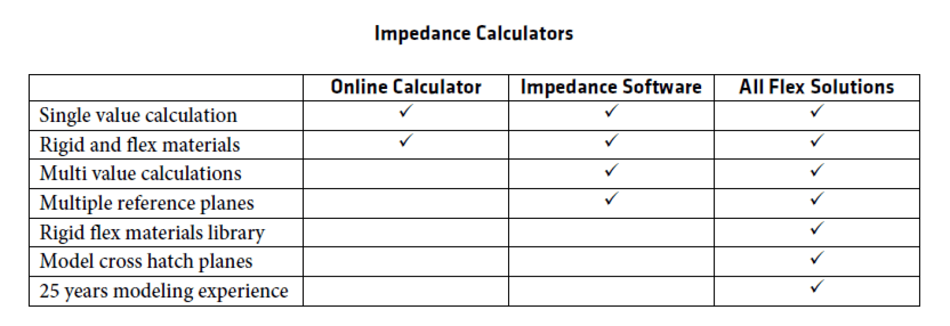
The Impedance Calculator capabilities across different platforms -

Circuit Geometry and Spacing Changing as They Transition to Rigid Section -
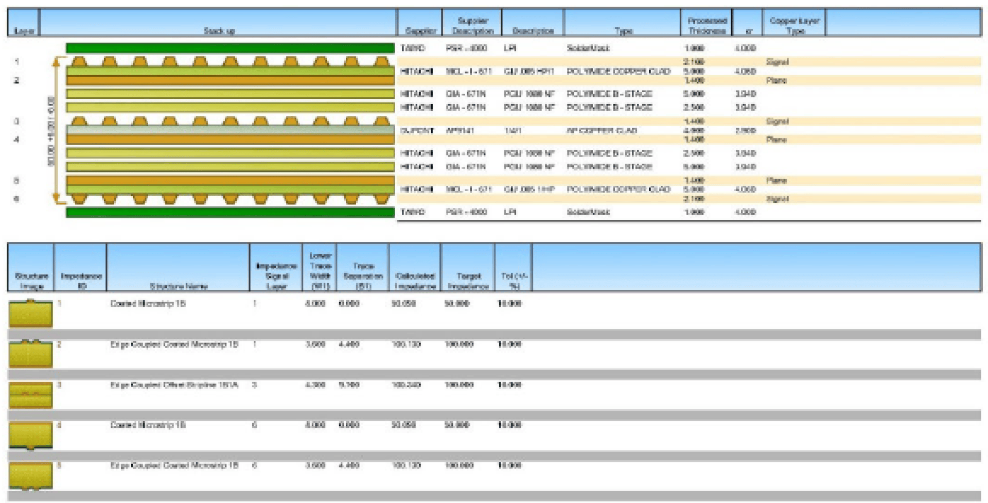
Example of Impedance Report - Rigid Section
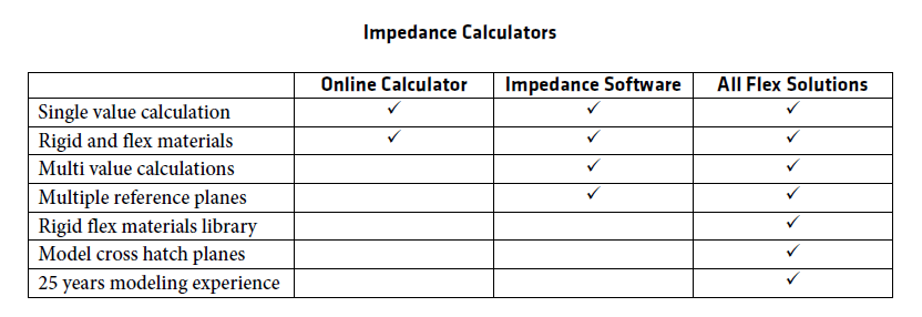


The dielectric materials in flexible sections of a rigid flex board are different than rigid laminates and offer better electrical performance. The coverlayers and bondplys also offer better electrical performance than the hardboard layers. These materials have varying dielectric values and should be modeled in software that is designed to predict how each of the dielectrics, reference planes, and circuits relate to one another.
Trying to do this in a rigid flex design using free online impedance calculators almost always returns false values. There are just too many interactions to use single-value calculators. Added to this, some of the material suppliers give global dielectric values when the value can differ due to core thickness, resin content, and signal speed.
The best solution is to purchase software, which is available as a standalone product or is often included/built into some of the more popular CAD PWB layout tools. The software is not inexpensive, but it is far more accurate than the free online tools.
Whether you decide to purchase the software or not, it is always wise to involve All Flex Solutions at the start of your design to either predict the impedance values or to double-check your work if you use your own software. All Flex does impedance modeling on rigid flex designs dozens of times a day, and we have a material library with dielectric values for every material; so we will know all the impedance values for every thickness of every dielectric we use.
If you are looking to improve the flexibility in the flex sections of your rigid flex board, All Flex Solutions is experienced with using cross hatched reference planes. Cross hatching impedance reference planes in the flexible areas of your part makes them dramatically more flexible and are still able to achieve your desired impedance values in high speed applications up to 10 GHz. All Flex Solutions has the expertise to show you how to incorporate cross hatching in your impedance reference planes.
For each impedance value that you want to be modeled, share the value you desire, the type, including tolerance, characteristic, or differential, on what layer(s), what speed the signal is at, what layer(s) are the reference planes, and any mechanical considerations, e.g. the board can't be thicker than .062", etc.
There are three important differences to keep in mind with impedance modeling of rigid flex circuit boards.
The first is that often, with the flexible laminates, the typical thicknesses of .001", .002", .003" for the flexible laminates are not thick enough to provide the typical desired impedances. Often thicker flexible materials are required. Unlike rigid laminates, the cost of thicker flexible laminates can rise quickly. One way of avoiding the higher cost of thicker flexible laminates is to employ cross hatched reference planes, which allow you to reduce the dielectric thickness and/or increase line width to aid manufacturability. You should take care to specify only those impedance values that are required.
The second is that the values, trace widths, and spacing will be different in the flex sections than they are in the rigid sections. All Flex can provide you with a model showing both calculations whenever you have impedance requirements in both the flexible sections of the board and the rigid sections. As a designer, you will need to neck down the circuits to their correct geometries and spacing. The neckdown should occur .050" or more into the rigid board(s) to prevent stress on the circuits at the neck down area, at the flex to the rigid transition area.
The third thing to keep in mind is that with rigid flex designs, the number of impedance values can multiply quickly -- each value often needs modeling and testing in the flex as well as the rigid sections of the board. Because of this, and each value needs to be tested in the impedance coupons that are built into your part's production panels, the size of the coupons can grow very large, very quickly. The larger the impedance coupons on the panel, the fewer number of parts that can fit on the panel, ultimately increasing your cost. It is wise to specify on your print, only those circuits that you truly need tested. You and/or your fabricator can model all the values you want through the whole PWB, but only put on the print the values you truly need and would like tested as well.
There are many other nuances to modeling and predicting impedance circuit performance, particularly in rigid flex PCBs -- the length of your circuits, cross hatch pattern and pattern angles, air gaps in unbonded flex constructions, flex versus rigid performance, etc. It is wise to get assistance from All Flex Solutions on your rigid flex impedance requirements.
Material layup:
If you molded the impedances as described above, you probably are 90% of the way toward your material layup. The report will give you the material cross section, with copper thicknesses, material thicknesses, dielectric values, etc.
If you don't have any impedance values to model, or you just need a straightforward material layup, ask All Flex Solutions for their recommendations. Here is what they will want from you to get started:
- The overall number of layers in the rigid section(s)
- Desired copper thicknesses in the rigid section(s) - Innerlayers and outerlayers with plating
- Number of layers in the flexible section(s)
- Desired copper thickness in flexible layers
- If there are three or more layers in the flex section - do you want them bonded together, or unbonded? (This can affect the ability to use a layer as a reference plane)
- The desired overall thickness of the rigid board(s) - over laminate, over plating, over soldermask?
- Materials desired - FR4, polyimide, etc.
- Final finish
- Any special requirements - UL, RoHS, lead-free assembly, REACH, halogen free, etc.
All Flex will provide you with a good material layup as a starting point, that you can refine from there.